- Home
- Product Categories
- Weather
- SparkFun Humidity and Temperature Sensor Breakout - SHT15

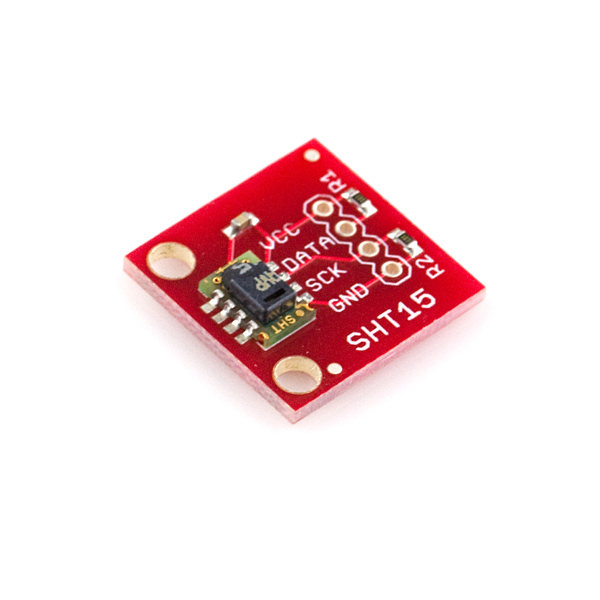
SparkFun Humidity and Temperature Sensor Breakout - SHT15
This is a simple breakout board for the SHT15 humidity sensor from Sensirion. The SHT15 digital humidity and temperature sensor is fully calibrated and offers high precision and excellent long-term stability at low cost. The digital CMOSens Technology integrates two sensors and readout circuitry on one single chip.
These sensors are really impressive! Very sensitive and straight forward to use. Board comes assembled and tested with the SHT15.
- Precise data logging
- Transmitters
- Automation & process control
- Building control and HVAC
- Test & Measurement
- Medical
- 2 factory calibrated sensors for relative humidity & temperature
- Digital 2-wire interface
- Precise dewpoint calculation possible
- Measurement range: 0-100% RH
- Absolute RH accuracy: +/- 2% RH (10...90% RH)
- Repeatability RH: +/- 0.1% RH
- Temp. accuracy: +/- 0.3°C @ 25°C
- Fast response time
- Low power consumption (typ. 30 µW)
- High precision sensor at low cost
- Leading CMOSens Technology for superior long-term stability
SparkFun Humidity and Temperature Sensor Breakout - SHT15 Product Help and Resources
Humidity-sensing LED Flower
October 28, 2014
How about that humidity? This tutorial shows how to add sensing capability to the 21st Century Fashion Kit's RGB flower project.
Core Skill: Soldering
This skill defines how difficult the soldering is on a particular product. It might be a couple simple solder joints, or require special reflow tools.
Skill Level: Noob - Some basic soldering is required, but it is limited to a just a few pins, basic through-hole soldering, and couple (if any) polarized components. A basic soldering iron is all you should need.
See all skill levels
Core Skill: Programming
If a board needs code or communicates somehow, you're going to need to know how to program or interface with it. The programming skill is all about communication and code.
Skill Level: Rookie - You will need a better fundamental understand of what code is, and how it works. You will be using beginner-level software and development tools like Arduino. You will be dealing directly with code, but numerous examples and libraries are available. Sensors or shields will communicate with serial or TTL.
See all skill levels
Core Skill: Electrical Prototyping
If it requires power, you need to know how much, what all the pins do, and how to hook it up. You may need to reference datasheets, schematics, and know the ins and outs of electronics.
Skill Level: Noob - You don't need to reference a datasheet, but you will need to know basic power requirements.
See all skill levels
Comments
Looking for answers to technical questions?
We welcome your comments and suggestions below. However, if you are looking for solutions to technical questions please see our Technical Assistance page.
Customer Reviews
5 out of 5
Based on 2 ratings:
working fine and fast
easy to read accurate sensor for home use!
Does the job needed
Very cost effective sensor to monitor both humidity and temperature in an experimental instrument chamber,
The sensor soldered on the breakout board needs to be reconditioned for accurate readings. From the SHT15 datasheet:
IMPORTANT: After soldering the devices should be stored at >75%RH for at least 12h to allow the polymer to re-hydrate. Otherwise the sensor may read an offset that slowly disappears if exposed to ambient conditions.
I did this by leaving my SHT15 in a ziploc bag with a cigar humidifier rated at rh 84%. You could also us a baggy with a small cup of damp salt. Before reconditioning the SHT15's readings were -7% what they should be. Now it's perfect. This is something I wish Sparkfun would do in house.
Thanks. No way I'm buying something this expensive when SparkFun hasn't even bothered to notify folks about this, nor do the acclimatization for us!
Please see my comment at the bottom of the page in response to Kilo's comment.
Has this issue been addressed by Sparkfun since this post?
We have been reconditioning these sensors for a number of years now. All units of this sensor go through the reconditioning process in our custom built humidor. If you find that your sensor readings are off, you may still want to follow this process yourself to recondition the sensor again.
I would like to recommend (suggest) a pcb redesign of this board so that it will include the two smalls hole that the SF1 filter require. And a second thought is to (optional) include a RJ45 socket. In case someone wants to physical place inside a radiation shield, and if used with the USB weather board, then i can also suggest a RJ45 socket addition at the USB weather board, in order to connect to.
Seconding the mounting holes for the SF1. I don't care much about the RJ45, which would make it bulkier and even more expensive than it already is.
Also, when you redesign the board, could you relabel DATA and CLK as SDA and SCL? After all it's an I2C interface, and that's the standard way to refer to data and clock in I2C. (The datasheet doesn't seem to mention I2C, probably because it's a Philips trademark.)
The datasheet says both sensor elements (RH% & T) are impervious to water vapor or liquid immersion, other than affecting the sensor's readings for a time until things dry out. These do not like chemical vapors so beware. I'm using both SHT15 and SHT75's but 75's for better repeatability in humidity ambients below 10%. SF does not offer the 75 on a breakout and you will have to add a 3-5k external pullup to the dat line to make them accurate or they will give erroneous data if not terminated properly, and set the sample interval to 8 seconds or more to allow for best conversion resolution. The 11's and 15's require both a pull up and pull down resistor for best stability but all three are signal protocol compatible i.e. interchangeable. I have about two dozen of these now monitoring various factory ATE system internals and environments at the UUT stations and these are perfect for the application because they bear traceable calibration from Sensirion, making them worth the extra expense for this app. I have had no trouble with them reconditioning by themselves in ambient air but it may take several days or weeks to settle out depending on how SF handled them before final packaging.
As per jacobfb's initial comments and subsequent posts (much obliged by the way for those) the SHT15 Humidity Sensors on both the Breakout Board, SEN-08257, and on the SUB weatherboard V3, SEN-10586, or most specifically the polymer surrounding the IC needs to be re-hydrated after reflow. From page 3 of the datasheet:
IMPORTANT: After soldering the devices should be stored at >75%RH for at least 12h to allow the polymer to rehydrate. Otherwise the sensor may read an offset that slowly disappears if exposed to ambient conditions. Alternatively the re-hydration process may be performed at ambient conditions (>40%RH) during more than 5 days.
And Page 4:
1.4 Reconditioning Procedure As stated above extreme conditions or exposure to solvent vapors may offset the sensor. The following reconditioning procedure may bring the sensor back to calibration state: Baking: 100 – 105°C at < 5%RH for 10h Re-Hydration: 20 – 30°C at ~ 75%RH for 12
To be honest we weren't initially aware of this procedure way back in 2010. I don't have any particularly poignant excuse either. It's possible we didn't get a detailed datasheet until after we started selling the sensor breakout, but regardless we didn't go back and check the datasheet. To be sure, that's our bad.
However, I can assure you that we are currently, and have been for some time now, re-hydrating the polymer around these ICs following the recommended reconditioning procedure. We gently hand clean each board with an alcohol solution, post reflow, then each board spends at least 12 hours in a humidity controlled environment. The boards are then tested, and sent off to be packaged in ESD sleeves as quickly as possible. Here in Colorado we are lucky to have a dry environment, which is good for most of our parts and boards. In this case our surroundings aren't to our benefit so we do our best to handle these boards, specifically these ICs, properly. We weren't aware of this issue until customers spoke up, so thanks for keeping us on our toes and keeping us honest. And very sorry for the delayed reply.
Great product, you guys. On your next revision, would you please include on the PC board two small holes for mounting the SF1 filter cap? Thanks.
the SHT sounds like such a hassle why not get the honeywell HH 4030, get your rig up and running and not worry about I2C or condensation damage. Does sparkfun carry the HH4031?
Depends upon what you're interfacing to and your choice of hardware I guess but with a micro that already has native I2C it makes it so easy just to put a device such as this out on the bus and simply read real numbers that mean something.
Perhaps time to replace this by a breakout board for the Sensirion SHTC1? The SHTC1 costs only 1/10th the price of the SHT15!! Granted, you'll need a 1.8V regulator on the BoB, plus level shifters (2 MOSFETs), but the total cost will still be a fraction of the current board. USB 42 is simply too expensive, even for the excellent specs of the SHT15. BTW, the SHTC1 has comparable specs.
SF, can we have a breakout board for the SHT21? Mucho, mucho cheaper than the SHT15!
The sensor itself sells for USD 29, then this little board is too expensive. Apart from the SHT15 there are just three passive components which cost a cent each.
I have a few comments, in case you do a redesign. 1. Add bypass cap 2. It's crazy that you have pull-down resistors. To make it compatible with any kind of I2C you really want pull-ups. Or at least some options. 3. There's a lot of unused PCB there. Since PCB is hygroscopic (I think), it will cause humidity and temp readings to be retarded as the PCB responds to the ambient conditions. It would be much better to cut down the PCB in a style similar to a SHT75: put the device on a small "island" of PCB, isolated from the connector part of the board with a narrower "neck" of PCB.
And there's even a driver in Linux for this guy. "< > Sensiron humidity and temperature sensors. SHT15 and compat."
I found a digital relative humidity and temperature sensor TH02 in http://www.hoperf.com/sensor/app/TH02.htm with very lower price.
The reason the HopeRF part is cheaper is probably that it is less accurate. BTW, while I like Hope's RF modules I don't like that Hope refuses to give prices on its site. That neither Digikey nor Mouser seem to carry the TH02 doesn't help either. Do you know how much the TH02 is in ones?
sf price is cheaper than ebay for this part, good job boys.
You guys should make a breakout for the Si7005-B-GM1R from Silicon Labs. It seems like a solid temperature and humidity sensor with a filter to keep out dust/liquids at 1/4 the price of the SHT15.
DIY replacement for sensor cap: I recently purchased the SHT15 breakout board and added it to my proMicro Barometer project. I had no trouble getting it working using the practicalarduino / SHT1x code from Github written by Jonathan Oxor (June 16, 2009). To protect the sensor, I wrapped a 6 mm strip of plastic from those very thin plastic bags used in the produce department. I just wrapped a single layer over the sensor and tied the strip behind the board. The sensor is still responsive when I breath on it so the plastic is not a complete moisture barrier but should help protect the sensor from dust.
Can anyone tell me why the SHT15 sensor would be preferable over this one? https://www.sparkfun.com/products/10167
The 4X cost difference is not being explained well in the descriptions.
Thanks!
I think the SHT15 comes pre-calibrated from the factory (calibration offsets in build in flash element) so it's got better accuracy out of the box.
Does Sparkfun consider a breakout-board for the SHT21 sensor, temperature + humidity, and fully I2C operated?
Has SFE started calibrating these after soldering as mentioned by jacobfb back in April 2010? or do I still need to calibrate these?
I know this is a delayed response, but we have started re-calibrating them in-house (seen Kinch's response below). If you are running into strange readings with this sensor however, it won't hurt anything to try re-calibrating it yourself.
Hi all,
Last week I bought a Arduino Duemilanove board and a SHT 15 breakout from Sparkfun.
I use the practicalarduino / SHT1x code from Github written by Jonathan Oxor (June 16, 2009).
At my job (I work on a technical laboratory) I placed the SHT15 sensor together with another commercial
temperature / humidity sensor above a hermetic closed saturated sodium chloride solution.
The theoretical value of the humidity of the saturated sodium chloride solution at 20 °C is 75,5%.
I measure with the commercial temperature / humidity sensor above the saturated sodium chloride solution an temperature 21,2°C and 75,0% humidity.
With the SHT15 breakout I measure above the saturated sodium chloride solution an temperature 21,3°C and 47,5% humidity!
Before the measurements I conditioned the SHT15 breakout 20 hour with >75% humidity.
What happens?
Who can help me?
Jack
The Netherlands
I bought one Humidity and Temperature Sensor - SHT15 and I used the CCS C Compiler (http://www.ccsinfo.com/) but I have several erros in the C code for example in the declaration #pragma origin 4, I got the error Invalid Pre-Processor directive can someone help me?
Hi. I just brought one of these, however after connecting it up and getting readings, I am a little disapointed with what I am seeing...
By "Fast response time < 4 sec" - does that mean its less than 4 seconds from asking it the temp/humidity to it giving it to you, or is it < 4 seconds to detect the current temp/humidty from changing location (ie inside to outside)... ?
I assumed it was < 4 seconds to give you an accurate temperature after changing location... however when I took it from our 23 degree living room, to outside which is about 4 degrees with a thermometer I have, it took more than 5 minutes for the temperature to begin reading in the right range... however that said, the temp sensor didnt show less than 10 degrees. I am a little unsure what is going wrong exactly.
When you blow on the sensor, the humidity changes quite prompty, however the temperature just takes forever to change. Why is this?
I have this plugged into an Arduino and am using the SHT15 library which is available on the arduino website. It worked first time, however its just incredibly slow and it doesnt seem accurate.
Do I have a faulty product or am I doing something silly?
James
The specs for the sensor may say ~4 second response, but that is for the elements internal to the sensor alone.
Once the sensor is mounted to something like a breakout board inside a case, with leads attached, the assembly becomes an extension of the sensor, the effects of which manifest as thermal bulk with/without conductive effects that responds much slower than the sensor element alone.
Best metrology practices should be observed by allowing the sensor assembly to reach equilibration to ambient conditions for best precision of the measurement...as much as an hour depending on how much bulk is in the assembly, and how much uncertainty in the measurement is tolerable.
This is where you get to 'play' with the module to empirically characterize your creation.
As with so many things in technology, there are caveats to using such devices. For example, if you are sensing rapidly changing conditions, having the sensor mounted to a large substrate (in effect a heatsink) and inside a case with no perforations to allow ambient to penetrate the sensor, you limit the accuracy and response of the sensor, possibly to the point of rendering it dubious.
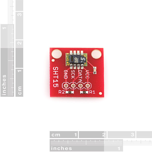
Scuse my ignorance but I'm only just starting to play around with I2C but on this board R1 goes to VCC and R2 goes to GND.
I thought that both resistores on I2C were pull-up, wired to VCC. Does anyone know the reason for it on this board.
This is NOT I2C, but 80% of it. Mainly the sensor pulls down SDA to indicate conversion complete. An existing bitbang (or something like the USI assist on the ATtinyx5) can be easily adapted to talk to this.
Sparkfun may want to consider changing the 10K pull-up resistor on the data line to something like 4.7K or 2.2K instead.
The current 10K pull-ups cause quite a bit of slew on the data line and limit speed. I'd prefer the trade-off of added current draw when transmitting on the bus over the lower data rate possible with higher value pull-ups.
It'd be nice to have an updated set of pdf's for this part. Also a dimensional drawing showing hole placement.
The boards that are shipping now don't match the photo or the schematic. They're red instead of green, which is awesome, but the resistors marked "not populated" are now populated. I had a frustrating time figuring out that the pull-down resistor on SCK was sinking enough of my clock that the sensor itself was ignoring it.
So test the board in your circuit before you install it in a way that blocks those resistors from being removed.
Also, I recommend Mouser 651-1725672 as a really tidy connector that solders directly onto this board. It dwarfs the sensor, but if you're running a cable to the sensor mounted inside an enclosure, it's nice to have screw terminals.
Everyone should take note, even though its advertised as a 2 wire, or i2c interface, its not 100% compatible... but once you work around the differences, its a dream to work with
Or, get the most sensitive sensor they make - ST75 I think - which has leads metric spaced leads (1.27mm) already attached for $32ish a pop from newark. Just got 10 myself for a discount plus used some 10% off coupon code.
The thing works great, though the temp reading takes longer than the humidity - and I really dont know what I need 14 bits of precision for something that's only +/- 1.8% accurate.
They also give you a non-linear curve fit equation and another one that does temperature compensation for humidity. Very sensitive - i can blow on it from 5 feet away and it notices.